Many processes use gas-liquid phase boundaries in reactors, from lab to production scale.
When assessing and designing a process, in particular processes when intrinsic chemistry is much quicker than mass transfer across the phase interface, the observed process rates are often limited by the gas-liquid interfacial surface area.
The interfacial surface area is fundamental for improved reaction efficiency to maximise contact between the gas and liquid, meaning it is a common metric used to compare reactors and estimate process performance.
Download pdf
Case Study # 04, rev 6,
3 Sep 2021, By Dr Nikolay Cherkasov
What determined the rate of gas-liquid reactors?
The rate of gas dissolution is proportional to the concentration difference: how much gas could be dissolved and how much is dissolved. The proportionality coefficient, kLa is the mass-transfer coefficient.
Gas saturation is fixed in practice dependant on temperature and pressure, or the existing gas concentration (often determined by the process requirements). What you could do is to use the reactor with the highest kLa to maximise the performance of the process. Doubling the kLa value, you could double the product throughput.
For fast reactions (such as CO2 absorption by an alkali), the rate is often determined by the interfacial surface area.
Gas-liquid processes:
- Catalytic hydrogenation
- Gas scrubbing
- Catalytic oxidation
- Enzymatic oxidation
- Aerobic digestion
- Fermentation
- CO2 capture and removal

Data for the batch reactor
There is plenty of data accumulated for batch processes. These include know-how on operating and servicing batch reactors and plenty of research papers that cover all aspects of batch.
A few examples (picture) show several papers with correlations that describe how the interfacial area depends on operating parameters.
The key parameters that affect the gas-liquid interfacial area are:
- Specific mixing power (in W/L), the mixing force introduced by agitators.
- Superficial gas velocity (in m/s), the velocity gas would have travelled being in reactor alone.
Rapid mixing agitators and high-velocity gas streams substantially increase the gas-liquid area, often resulting in fast processes.

Predictions and correlations
Lopes de Figueiredo and Calderbank [1] suggest the simplest correlation to study and predict the gas-liquid area:
, where p is the agitation mixing power (in W), VL is the liquid volume (in m3) and Qg is the superficial gas velocity (in m/s). The resulting superficial area in (m2/m3) is obtained from values that are easy to estimate.
The liquid volume is incredibly straight forward to afind out, a first approximation is the reactor volume. We can focus on surface mixing as the mixing power is strongest at the gas-liquid interface. In practice, a good estimation could be obtained from the equation: , where is the fluid density (in kg/m3), is the impeller rotation rate (in s-1), is the impeller diameter (in m), and is the power number (well tabulated for various impeller types, typically around 3 to 5). Substituting these values, we estimate the mixing power. The superficial gas velocity is another simple parameter to calculate – we divide the total volumetric gas flow rate introduced by the apparent reactor cross-section area.
Experimental measurements of the gas-liquid interfacial area
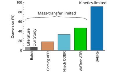
aWe have studied the gas-liquid area in the SABRe system using a conventional method of studying CO2 absorption by a NaOH solution. The experiment is simple – we introduce CO2 gas and measure the unabsorbed gas. Doing some calculations described in our paper[2], we determine the interfacial area.
We could compare the obtained data and the data expected by the correlation, yet correcting them for (i) increased process temperature that decreases CO2 solubility compared to collated data, and (ii) large concentration we used that results in high viscosity and rapid reaction rates. Both factors require the correlated areas to be a factor of 0.36 lower.
The comparison of the predicted and measured data show excellent agreement; within ±25%, highlighting the reliability of the SABRe system. It is an excellent agreement between the 1978 paper on batch reactor when applied to SABRe.
The SABRE system provides large gas-liquid interfacial area predictable up to 5,000L reactor volume to maximise the reaction throughput and selectivity.

References: [1] M.M. Lopes de Figueiredo, P.H. Calderbank, Scale-Up Specified of Aerated Mixing Vessels Oxygen Dissolution, Chem. Eng. Sci. 34 (1978) 1333–1338. [2] L. Chatre, J. Socci, S.J. Adams, P. Denissenko, N. Cherkasov, Design of 3D-printed structures for improved mass transfer and pressure drop in packed-bed reactors, Chem. Eng. J. 420 (2021) 129762.
The SABRe system (available in steel, Hastelloy or glass) is suitable for a wide range of chemical applications. Combining simplicity with superb reaction control, SABRe is the best choice for simple, safe and cost effective chemistry.
What can the SABRe do for you today? Get in touch and arrange a trial.
Other SABRe case studies:
Improvement of enzymatic oxidation in the continuous Scalable Agitated Baffle Reactor (SABRe) system
Case study on enzymatic oxidation by Prof John Woodley
Steven’s oxidation with Vapourtec
1.4 kg/day multiphase oxidation obtained integrating SABRe system with Vapourtec’s R-Series
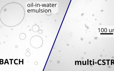
Consistent oil-in-water emulsions in continuous flow
Using a continuous multi-CSTR system allowed us to make droplets 2.5 times more uniform compared to a batch reactor
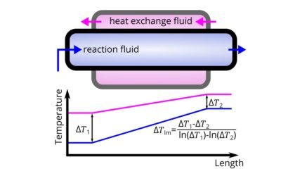
How to calculate heat transfer in continuous flow applications
Continuous flow (such as micro-reactors) are superior for exothermic reactions. How do you compute the thermal performance of a reactor?
Comparison of continuous reactors in enzymatic esterification
We showed superior performance of SABRe in the enzymatic (liquid-liquid) esterification.
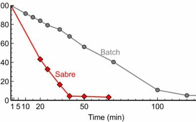
How residence time affects product quality in flow chemistry
How residence time is vital for throughput and product quality.